To control the game I'm using an old analogue PC joystick and Thrustmaster pedals, so I simply swap connections to play this. Obviously the original design calls for handlebars which I hope to buy very soon, but in the mean time it plays very well with the stick and pedals. The controls needed are wheel, accelerator, brake, coin input and start. The only one of these unavailable on the panel is the coin input, so I connect the original test panel and use the service button.
First, there are four power connectors, of the usual Sega 10-pin AMP type. As you can see there are four boards, and each one has a power connector. There are also three interconnecting cables between the boards.

The video and sound connectors are the same as those on Out Run. The video connector is on the lower large board and the sound connector is on the upper small board. The smaller boards are not just for sound though, they also hold many graphics ROMs, so if you're testing your boards and you can see the road but not the bikes, the problem is either power or a bad connection between the boards.
1 Red
2 Green
3 Blue
4 Sync
5 GND
6
1 Left
2 Left Ground
3 Right Ground
4 Right
5
6
This is the main 50-pin connector for the game's controls. Again it's similar to the other Sega games of the era. In this case there's no separate 20-pin connector for the controls, they're all together on this one connector.
| A1 | B1 | |||||
| A2 | B2 | Brake | ||||
| A3 | B3 | |||||
| A4 | Acc +5V | B4 | Angle +5V | |||
| A5 | Acc | B5 | Angle | |||
| A6 | Acc GND | B6 | Angle GND | |||
| A7 | B7 | |||||
| A8 | B8 | |||||
| A9 | B9 | |||||
| A10 | B10 | |||||
| A11 | B11 | |||||
| A12 | B12 | |||||
| A13 | B13 | Start Switch | ||||
| A14 | Service | B14 | Test | |||
| A15 | Coin 2 | B15 | Coin 1 | |||
| A16 | +5V (from PSU) | B16 | Start Lamp +5V | |||
| A17 | Coins GND | B17 | Start Switch GND | |||
| A18 | Coin Meter* | B18 | ||||
| A19 | Coin Meter* | B19 | ||||
| A20 | Start Lamp | B20 | ||||
| A21 | B21 | |||||
| A22 | Coin Meter* | B22 | Coin Lamp +5V* | |||
| A23 | +5V (from PSU) | B23 | +5V (from PSU) | |||
| A24 | Coin Meter* | B24 | Service and Test GND | |||
| A25 | GND (from PSU) | B25 | GND (from PSU) | |||
So to start with I connected the Test and Service buttons on my JAMMA harness to the test panel I received with my Space Harrier boardset.
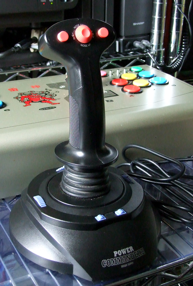
For the accelerator, brake and handlebars I already had the full harness so they're terminated with Molex plugs. Again, see my Space Harrier write-up to see how I completed that first. I later bought a different, better PC joystick, shown below. This joystick has the pins all wired up, even those which are not connected at the joystick end (in other words, a wire runs from the pin through the cable to the joystick, but the wire is left hanging and is not connected). This was of enormous benefit, since it meant I didn't need to run an external wire for the Y axis.
The best manual I've found for the wiring diagram is the Sitdown Wiring Diagram from KLOV. You can see that A16, A23 and B23 must be connected to the JAMMA harness to supply +5V to the board. A25 and B25 must be connected to ground. So you'll have a lot of +5V and Ground connections on your JAMMA harness, be careful that the +5V and Ground lines don't touch.
The four Coin Meter pins can again be safely ignored.
I plan to buy Super Hang-On when I get the chance, its main addition is the Turbo button, and I also hope to buy its control panel which I can use with both games.


No comments:
Post a Comment
Note: only a member of this blog may post a comment.